Timer Switch
Switches off the soldering iron* when the timer counts down
* or anything that uses 5A or less of mains power
The user interface on my soldering iron is a model of simplicity, it's a physical on/off button on the front which is super but you can forget to switch it off. There is a power LED but that's easily missed.
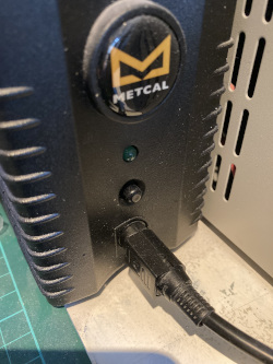
After getting back from holiday and noticing that I'd left the soldering iron switched on the whole time I looked around for something to turn it off with a timer.
There are lots of mains timer switches available, but nothing which quite works for my use case.
Some are just for turning the power on and off at certain times during the day

Some don't allow you to set the timer with enough resolution
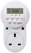
Some have horrible little displays with overly complicated user interfaces
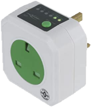
This one comes close but doesn't show the timer
The most common problems with the existing solutions were:
- Tiny lcd displays not easily visible at a glance
- Overly complicated interfaces which did more than I wanted without doing exactly what I wanted
- Non-wall mountable form factors (mostly they're 'through-plug' style)
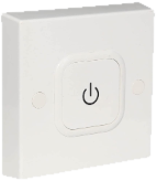
- Crazy prices (the closest match was this for 40 quid) but again, overly complicated UI
So I came up with some requirements:
| Requirements | |
|---|---|
| Electrical | Mains powered |
| Handle 1.2KW power (5A @ 240V) | |
| Replaceable fuse | |
| Compliant with safety regulations | |
| Physical | Wall mounted 'breaker' style |
| 80 x 80 x 40mm form factor | |
| Interface | As simple as possible, one click on/off |
| On-time can be increased/decreased on the fly | |
| Large timer display (visible from across the room) | |
| Beep to warn of impending shut off | |
| Configurable default on-time | |
| Power status LED indicator |
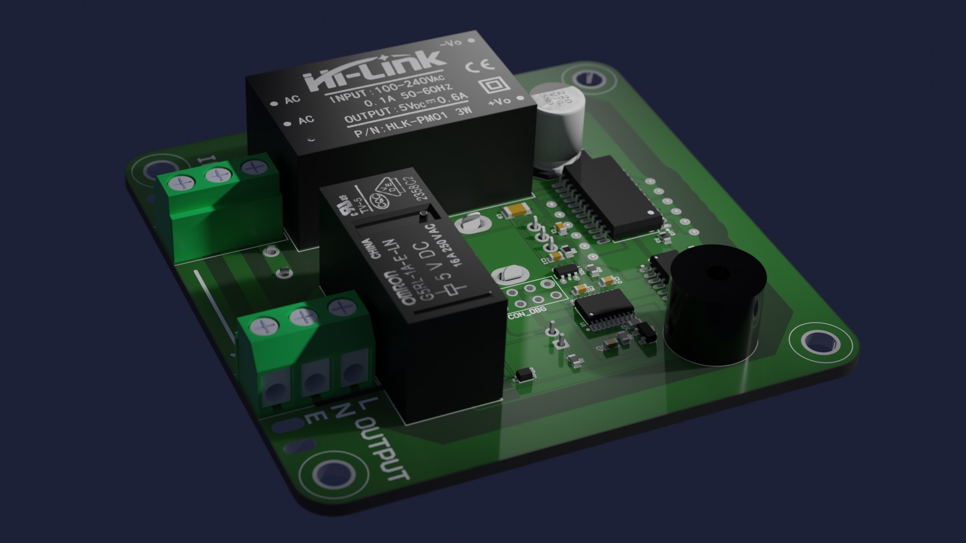
Overview
It's a very simple gadget using the crappiest STM32 MCU available, a push-button rotary encoder, a relay, and a MAX7219 to drive the display. Electronics are powered by a generic HLK-PM01 5V PCB mounted PSU. Separation/creepage distances between the 'hot' mains side and the rest of the board are maintained.
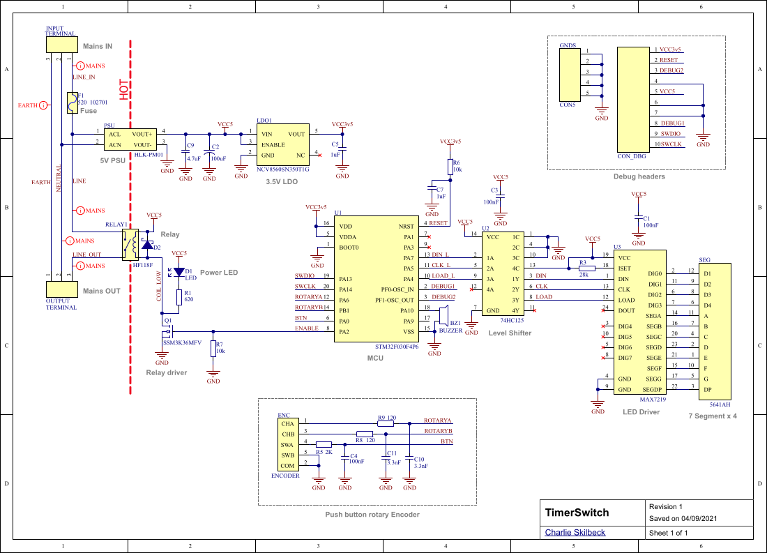
Schematic
The schematic is very simple and fits on a single sheet.
BOM
This was all done before the great component shortage so little thought was given to availability, but as of September 2021 all components are currently available somewhere, although pricing is a bit silly in some places. Note this BOM is just for prototyping, a real BOM has many more columns than this. Note that everything except the MCU, the MAX7219, the PSU and the relay can be substituted with any old generic part you can find.
Show the BOM...
| Designator | Quantity | Value | Footprint | Comment | Description |
|---|---|---|---|---|---|
BZ1 |
1 | - | PIEZO_BUZZER | BUZZER | Piezo buzzer |
C1, C3, C4 |
3 | 100nF | CAPC1608X07L | 100nF | Ceramic capacitor |
C2 |
1 | 100uF | CAPAE9585X105L | 100uF | Electrolytic cap |
C5, C7 |
2 | 1uF | CAPC1608X07L | 1uF | Ceramic capacitor |
C9 |
1 | 4.7uF | CAPC3216X07L | 4.7uF | Ceramic capacitor |
C10, C11 |
2 | 3.3nF | CAPC1608X07L | 3.3nF | Ceramic capacitor |
D1 |
1 | 20mA | LED | LED | 5mm through hole |
D2 |
1 | 20V 500mA | SODFL250X100-2L | DSF05S30U | Schottky Diode |
F1 |
1 | - | 5x20 FUSE | 520_102701 | Fuse speed F |
R1 |
1 | 620 | RESC1608X05L | 620 | Resistor 1% |
R3 |
1 | 28k | RESC1608X05L | 28k | Resistor 1% |
R5 |
1 | 2K | RESC1608X05L | 2K | Resistor 1% |
R6, R7 |
2 | 10k | RESC1608X05L | 10k | Resistor 1% |
R8, R9 |
2 | 120 | RESC1608X05L | 120 | Resistor 1% |
INPUT, OUTPUT |
2 | - | TERMINAL_BLOCK | TERMINAL | x3 terminal block |
Q1 |
1 | - | SOT95P230X110-3L | SSM3K36MFV | n-channel mosfet |
PSU |
1 | 5V 600mA | HLK-PM01 | HLK-PM01 | 5V PSU 0.6A |
RELAY1 |
1 | 240VAC/5A | G5RL-1A-E-HR | G5RL-1A-E-HR | Relay 5V |
ENC |
1 | - | PEC12R-4XXXF-SXXXX_1 | ENCODER | Rotary encoder |
LDO1 |
1 | 3.5v 150mA | TSOP95P280X110-6L | NCV8560SN350T1G | 3.5V 150mA LDO |
SEG |
1 | - | 5641AH | 5641AH | 4x7 Segment display |
U2 |
1 | - | SOIC127P600X175-14L | 74HC125 | 4 way level shifter |
U1 |
1 | - | TSOP65P630X120-20L | STM32F030F4P6 | Microcontroller |
U3 |
1 | - | SOIC127P1030X265-24L | MAX7219 | LED Driver |
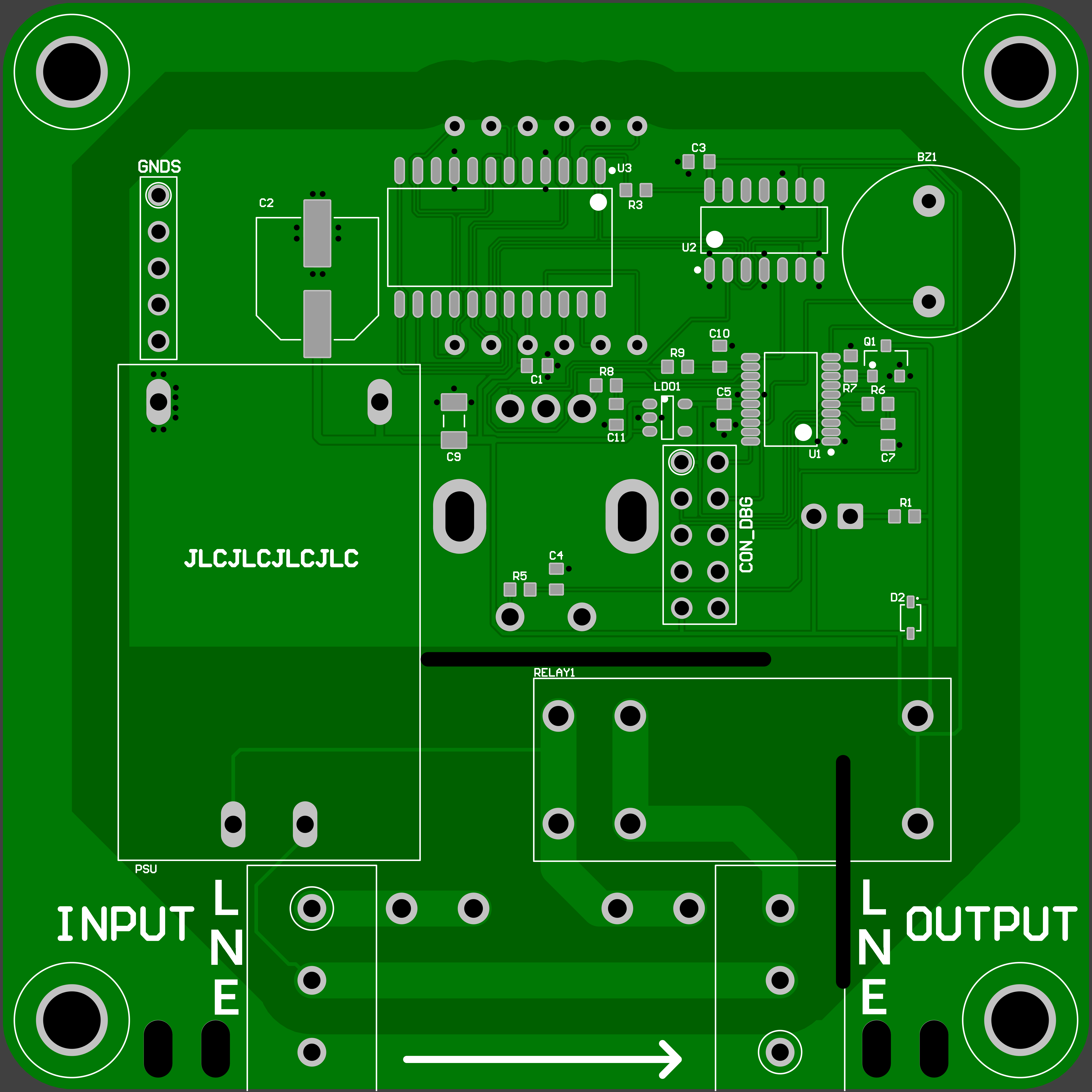
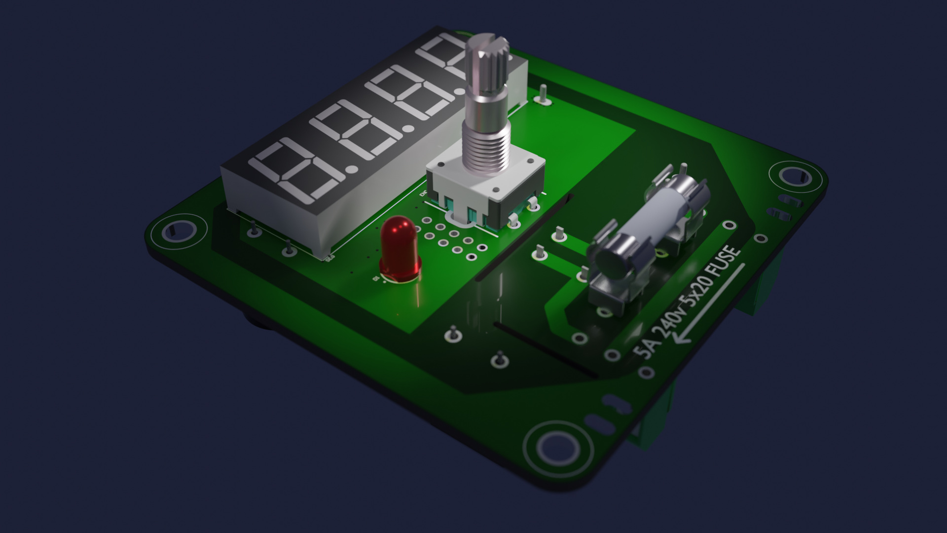
PCB
For such a simple board, 2 layers is fine and in fact the 2nd side of the board has only a ground plane, earth surround and some duplicated higher current traces on it. Note that the 'top' of the PCB faces the wall and the display and rotary encoder are on the 'bottom'. 2nd revision of PCBs from JLCPCB was bodge free after bringup.
Top
Bottom
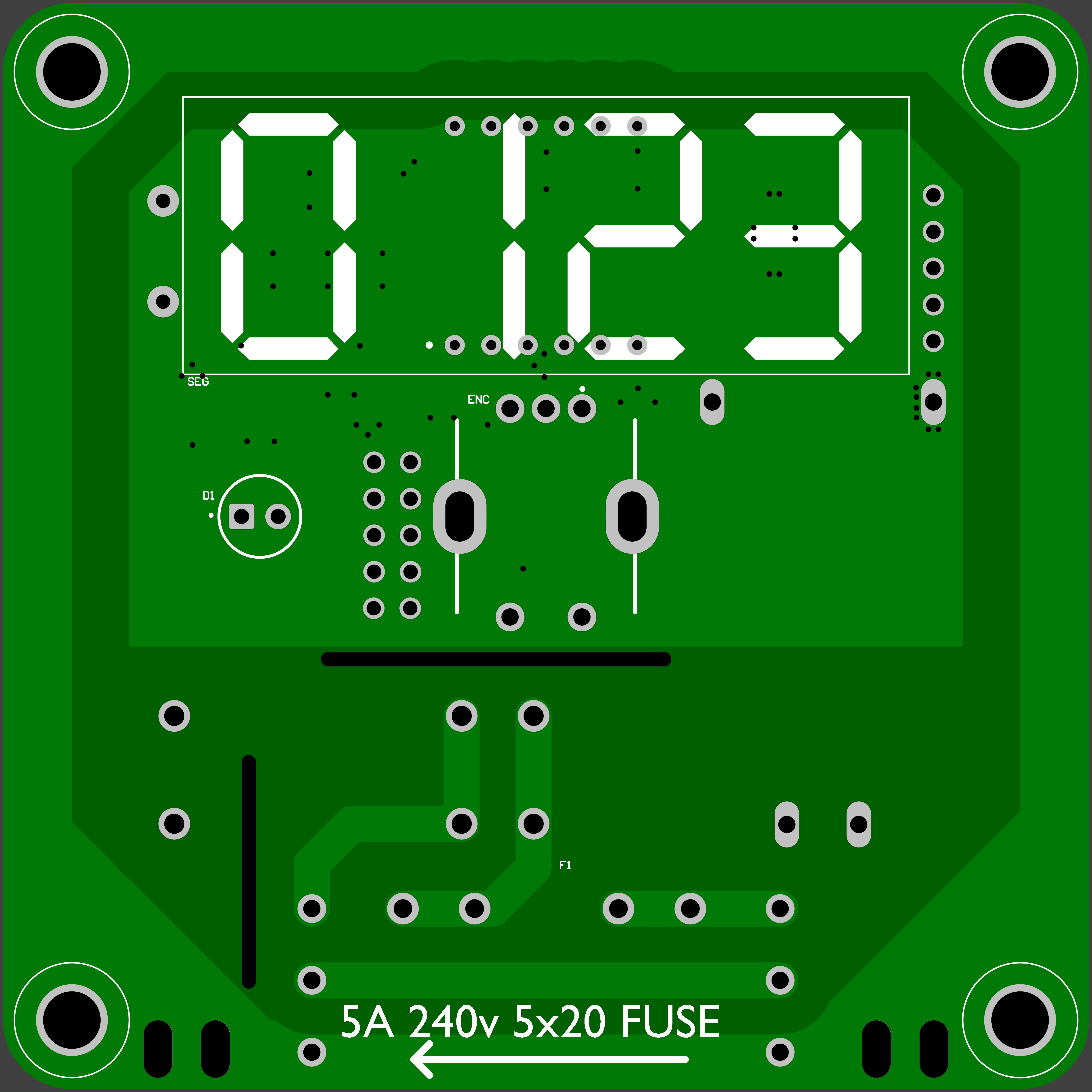
Note the PCB can carry up to 10A (and the relay can do 16A) but using a 5A fuse leaves a good margin. Gerbers are here, the zip file can be uploaded directly to JLCPCB order page to get bare boards.
Glamour shots
Firmware
The firmware is also quite straightforward, the relay is controlled with a GPIO via a mosfet, the MAX7219 is a simple SPI device and reading the rotary encoder is just a handful of lines of code. To save the settings through a power cycle I used some STM32 flash code from another project.
Enclosure
I used Autodesk Fusion 360 (when it was still free) to design the enclosure which consists of three parts: the back, the front and the fuse holder. It looks like this
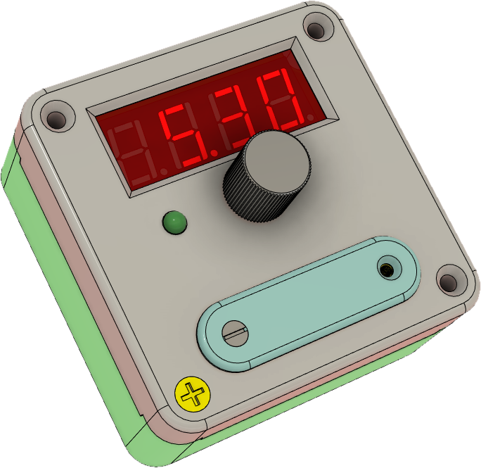
There's also a small slab of 3mm red perspex in front of the digits to make them more visible. Any old plasterboard screws are used for wall mounting, they attach through the base and then four other screws attach the front to the back. The fuse holder uses some tiny machine screws which go into some threaded inserts on the front. Sadly Autodesk are holding the files hostage since they changed the licensing model for Fusion 360 so step/stl files can't be extracted without paying them for a license.
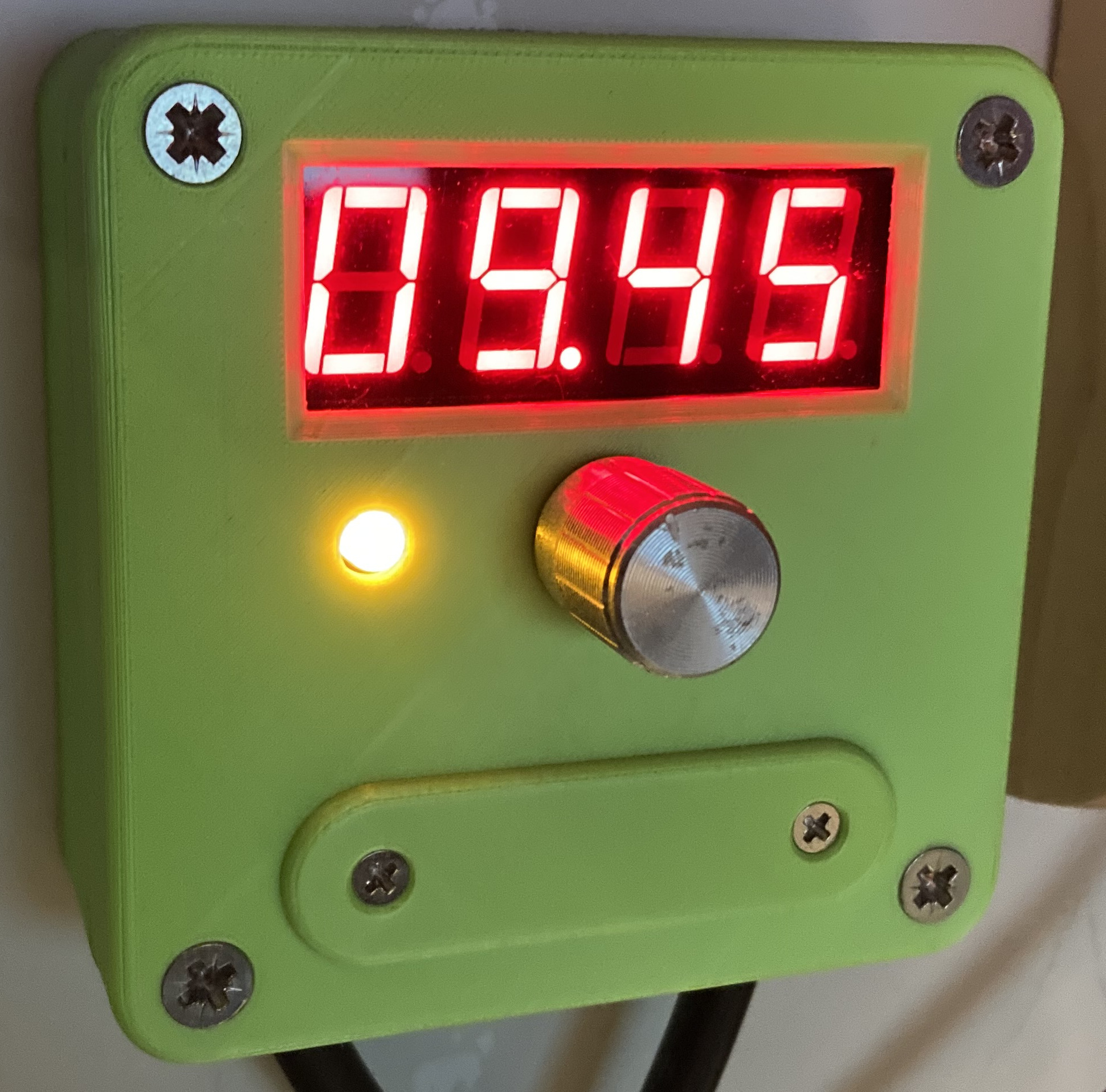
Conclusion
It works, I use it all the time, I haven't changed it since I mounted it on the wall and don't expect to need to. Making rather than buying something like this means I get exactly what I want and have some fun along the way so this goes in the success pile. And here it is in action (it's green because I was trying to use up a roll of filament)
Instructions
- Push the knob to toggle power on and off
- Twist the knob to increase or decrease remaining on-time
- Hold the knob down to enter menu mode
- Menu items:
| Item | Description |
|---|---|
set |
set the default on-time. This is what the timer will be set to when the power is switched on |
brt |
set display brightness |
beep |
set when the warning beeps start |
flsh |
set when the display starts to flash |
done |
exit menu |
- To replace the fuse
- unscrew the two front-mounted screws
- pull off the fuse holder
- take out the old fuse
- put the new fuse in
- insert the fuse holder
- screw in the two front-mounted screws